35+ frequency locked loop block diagram
Phase Frequency Detector AnalogRF IntgCkts. First pin3 and pin2 are the input pins that help us connect the input analog signal.
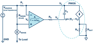
Evertiq High Side Current Sensing
This ensures that the local oscillator is at the same frequency and in phase with the remote one.
. Phase-locked Loop Block Diagram. It may also have a divider in the feedback path or in the reference path or both in order to make the PLLs output signal. To calculate the frequency stability for our OCXO in Hz of the LNB we either take.
The Phase Locked Loop PLL synchronizes a local oscillator with a remote one. Vco circuit phase locked loop driving frequency analog voltage synthesizer diagram block PDF A Self-bandwidth Switching Area-efficient PLL Using Multiplexer. Design working priciple theory Random.
Internal block diagram of LM565 PLL chip. 4046 datasheet locked cd4046. P072C Gearbox system locked in first gear P202B Short to ground in the tank heater.
4046 pll diagram phase loop lock project schematic 2212 control circuit site. PFD Waveforms Out of. Performance Study of FLL Schemes for a Successful Acquisition-to-Tracking Transition This.
It is possible for a PLL to have a phase offset between input and output but when locked the. Pll oscillator wave circuit frequency medium diagram sine phase circuits gr loop locked 2009 schematic low simple works. Block Diagram of Type 1 Phase Lock Loop.
The block diagram of the demodulation circuit is illustrated in. Type-1 Phase Lock Loop. Thus a 1 Hz change to the reference will result in 384 x 5 or 1920 Hz change in the LO frequency.
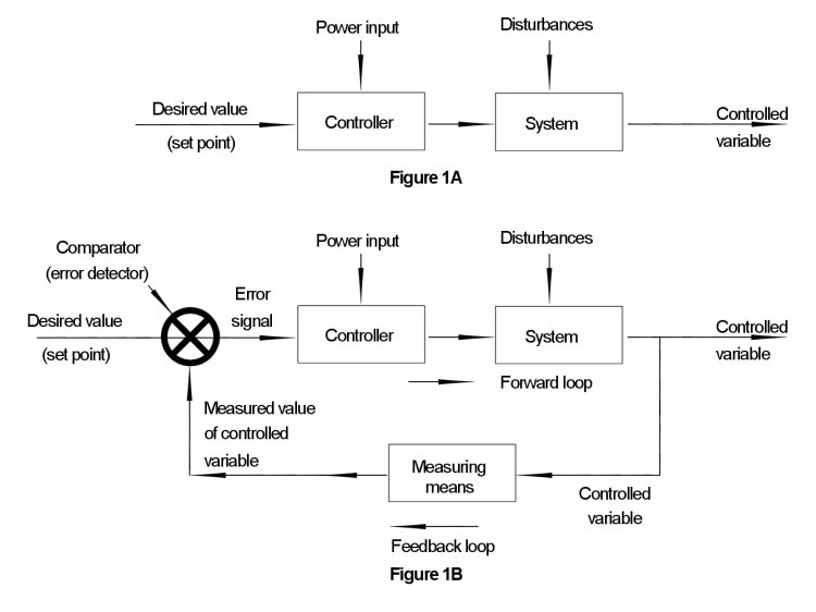
A Phase Locked Loop Working is basically a closed loop system designed to lock the output frequency and phase to the frequency and phase of an input signal. The block diagram of a PLL operating as a frequency synthesizer is shown in Figure 1 8. Download scientific diagram Block diagram of a typical frequency lock loop 7 from publication.
The illustration depicts a block diagram of a frequency-modulation circuit made up of a phase-locked loop. 565 Phase-Locked Loop Explanation. The error signal is then low-pass.
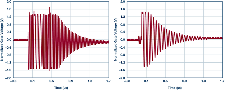
Figure 5 is a diagram which shows the relevant waveforms. System is out of lock and the frequency on IN is much higher than the frequency on IN. Pll fm demodulator circuit using xr2212.
A digital phase locked loop uses a digital phase detector. A phase detector compares two input signals and produces an error signal which is proportional to their phase difference.
Why Is Pll Used In A Microcontroller Quora
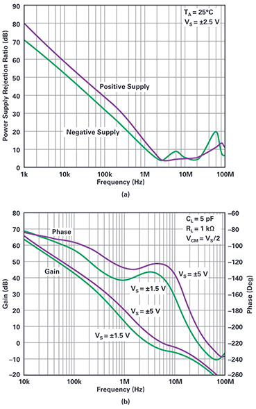
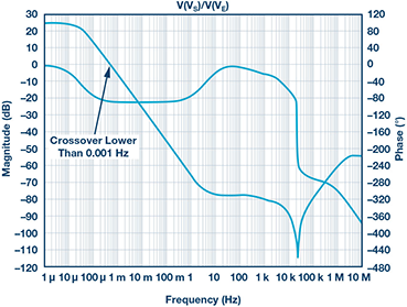
Evertiq Bootstrapping A Low Voltage Op Amp To Operate With High V
Evertiq High Side Current Sensing

Open Loop And Closed Loop Systems

Open Loop And Closed Loop Systems
Evertiq High Side Current Sensing
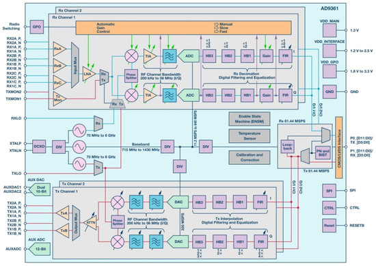
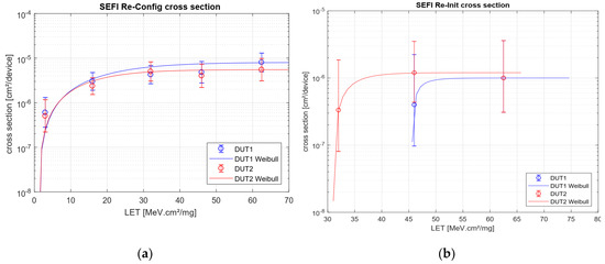
Aerospace Free Full Text Heavy Ion Induced Single Event Effects Characterization On An Rf Agile Transceiver For Flexible Multi Band Radio Systems In Newspace Avionics Html
Why Is Pll Used In A Microcontroller Quora

Ne567 Datasheet Tone Decoder Phase Locked Loop And Example Circuits Function Generator Circuit Simple Electronics
Open Loop And Closed Loop Systems
Why Is Pll Used In A Microcontroller Quora
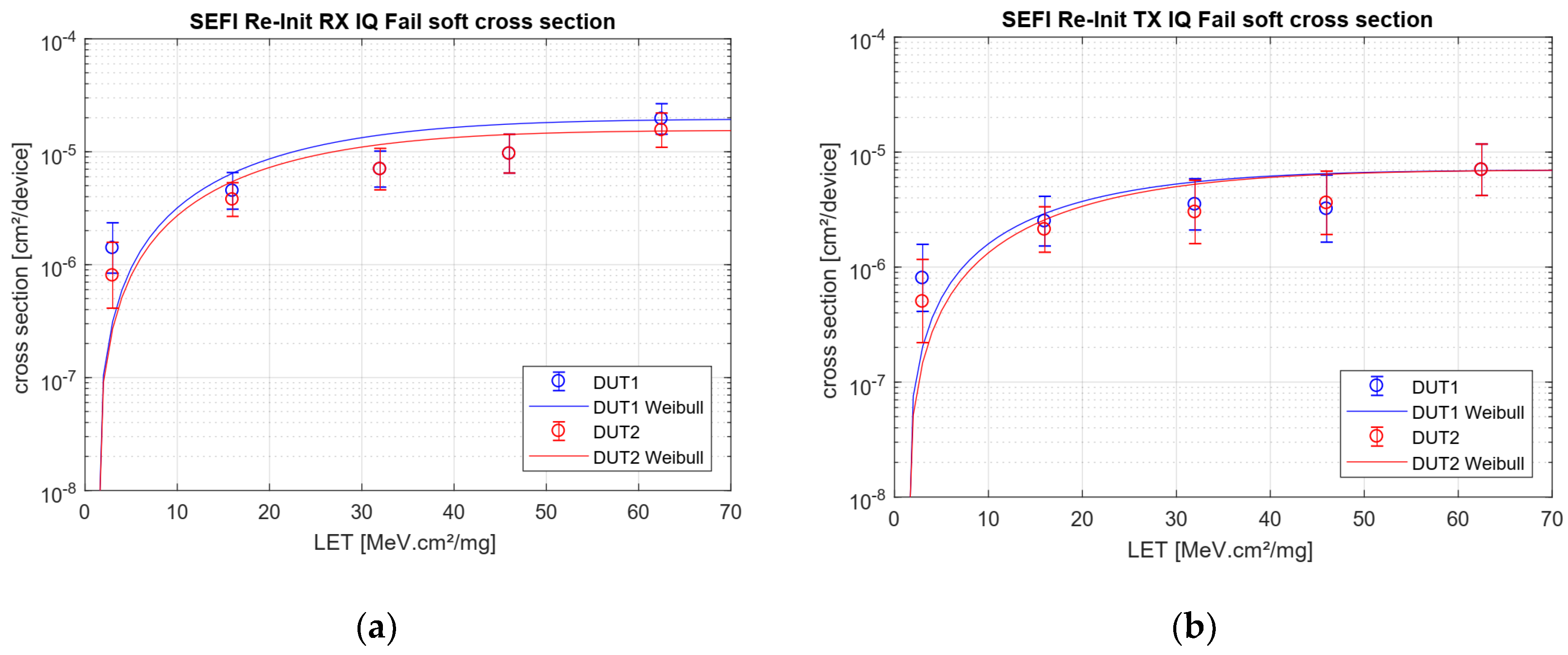
Aerospace Free Full Text Heavy Ion Induced Single Event Effects Characterization On An Rf Agile Transceiver For Flexible Multi Band Radio Systems In Newspace Avionics Html
Aerospace Free Full Text Heavy Ion Induced Single Event Effects Characterization On An Rf Agile Transceiver For Flexible Multi Band Radio Systems In Newspace Avionics Html

Ne567 Datasheet Tone Decoder Phase Locked Loop And Example Circuits Simple Electronics Function Generator Circuit
What Is Integrated Audio Codec Chip Quora
Aerospace Free Full Text Heavy Ion Induced Single Event Effects Characterization On An Rf Agile Transceiver For Flexible Multi Band Radio Systems In Newspace Avionics Html

Ne567 Datasheet Tone Decoder Phase Locked Loop And Example Circuits Simple Electronics Function Generator Circuit